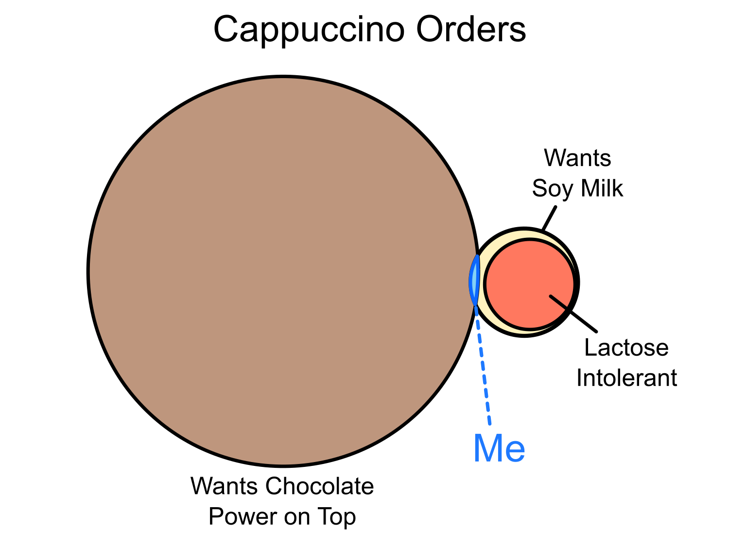
Look, Costa Coffee, it’s really quite simple.
Let:
| l(x) | x is lactose intolerant |
| s(x) | x wants soy milk in their cappuccino |
| c(x) | x wants chocolate powder on top |
Then:
Look, Costa Coffee, it’s really quite simple.
Let:
| l(x) | x is lactose intolerant |
| s(x) | x wants soy milk in their cappuccino |
| c(x) | x wants chocolate powder on top |
Then:
Having worked on a couple of software systems that required localisation for multiple countries, I’ve encountered many situations where, much to my dismay, I’ve needed to dip into the baffling world of international time zones. Time zones are one of those awkward real-world domains, the rules for which have evolved independently over many years across many different authorities. They are chock-full of arbitrary edge cases that fly in the face of the kind of neat, organised abstractions that software developers love. Tom Scott sums up the problems brilliantly in one of his videos from the Computerphile channel on YouTube, The Problem With Time & Timezones.
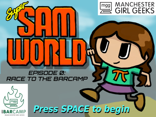
Last month I was asked very nicely by [Manchester Girl Geeks] organiser [Sam Headleand] if I would consider making a simple platform game for their BarCamp event. So after a bit of coding with [PyGame] I came up with:
A few years ago I wrote an ASCII diagram parser in Python. I never got round to blogging about it at the time, but now I want to finally get some of my thoughts about it down in writing.
Today I wanted to set up a quick web script; just something that ran on the Apache server I already had set up, took some query parameters and spat out a basic page in response. My usual go-to for this kind of thing would typically be PHP, because it’s so quick to throw together and deploy. But this time, I wanted to see what the Python equivalent would be. Is it possible to write a quick Python script, drop it on a server and have it just work? Well, yes, it turns out it is. Or very close, at least. Here’s how…
Recently I have been having some issues with sprites in the game I’m currently working on. It’s a 2D game and I’m using OpenGL to render textured triangle pairs for my sprites. Let me explain some of the caveats I’ve run into with regard to mipmaps.
I’ve been going to the Manchester Game Jam ever since the awesome Dan Hett started it up over a year ago at MadLab in Manchester’s northern quarter. It’s so much fun to turn up with a laptop, blast out a game idea over the course of a weekend and see how it turns out. Most of the time, what seems like a great idea on paper turns out to be a terrible idea in practice, once you can see it moving in the form of a prototype. Occasionally though, an idea will work, and at the last-but-one game jam this happened to me.
Recently, for the Manchester Raspberry Jam, I decided to write an extremely simple MUD game which could be run on the Raspberry Pi. The aim was to create something fun that might spark curiosity for someone learning to program. The code is up on GitHub.
Getting the server to work with Microsoft’s Telnet client that ships with Windows (or doesn’t, as is currently the case), proved to be a bit of a pain. In Linux I could connect to the server, type a command, and as I typed I would be able to see the letters appearing in my local terminal. When I hit enter, the server would receive the whole line I had typed. All good.
In Windows, however, the first problem I discovered was that the telnet client is no longer installed by default for Vista onwards. Vista / 7 / 8 users have to follow this guide to enable it.
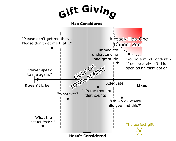
A despair-inducing variation on the classic detective game Cluedo (or Clue) for 2-6 overstuffed and resentfully blood-related players at Christmas time.
Rules of the game are the same as the standard version, but with the following additions:
It’s been 3 months since my post previous about the game I’m working on. This is the game that I’m determined to finish no matter what - a simple 2-player strategy game centered around a cannon-firing mechanic - think Worms but on an isometric map.
What’s happened with it since then? Well,
There’s something that’s bugged me for the entire time I’ve been using a PC. It concerns a fairly standard UI component that I’m sure you’ll be familiar with: the orderable table.
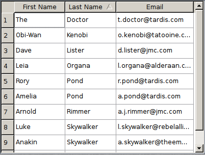
As you’re probably aware, a table like this usually holds rows of data which can be sorted by any of the table’s columns. Clicking on a column header will order the data by that column. Clicking this column again will toggle the order direction between ascending order and descending order. It’s a great idea. However, my issue has always been with the icon indicating the order direction.
Oh dear - I’ve been procrastinating. NSFW warning for some rude words in this post. Around a month ago Fiona and I stumbled across this blog post about an issue with Django. The post was very helpful and saved Fi a lot of headaches, so thanks to Harshad Sharma for that.
What caught my attention, though, was that fact that the post consists entirely of a rage comic. A rage comic, for the uninitiated, is an internet meme wherein a hilarious anecdote is retold in the form a crudely-drawn comic strip, usually full of cartoon facial expressions which are themselves internet memes. I joked that such a blog post, due to its entirely rasterised nature, would be difficult for a search engine to index. Difficult, that is, unless the comic’s semantics could be encoded as text-based data. Sometimes, a joke gets out of hand.
Making videogames has been a hobby of mine since since my mid teens. In fact, even before I learned to program I used to write choose-your-own-adventure stories based on games I had played. Yet, despite a long trail of unfinished projects, abandoned due to over-ambition, boredom or distraction, I’ve never released anything I would call a finished game. I’ve finished the occasional thrown-together competition entry for Ludum Dare, and now and again I’ve had the motivation to round off some small experiment into something functionally complete but too small in scope to be noteworthy.
You see, it turns out that making games is hard. Not just hard in the sense that it’s technically demanding, because after
I have the catchily-named Sony Ericsson Xperia X10 Mini Pro smartphone. The device runs a customised version of Android that Sony Ericsson developed to make better use of the unusually small screen size. Among the customised apps is a photo album which displays all the pictures taken with the device’s camera, ordered by date and grouped into months.
One annoyance I’ve found with this app, however, is the way the photo ordering is achieved.
This is a project that I decided to undertake one day and which is only semi-serious. It exists mostly due to both my recent curiosity with Parsing Expression Grammars, and a stubborn refusal to give up on a blatantly terrible idea. Oh, and a love for John Gruber’s Markdown and the principles behind its design.
Sometimes, a simple message is not a sufficiently productive way of communicating with someone. After a small number of back and forth emails, someone will decide to pick up the phone or meet in person to have a face-to-face conversation. This way, the feedback loop is shorter and each question can be devised based on the previous answer received in order to exchange the necessary information between participants.
Face to face conversations are not always possible, however. And waiting for
Over the years, Twitter has become increasingly popular with indie game developers. At some point, the hashtag #ScreenshotSaturday was invented to tag screenshots of game developers’ work in progress each week. The hashtag is a great way to get a sneak peek at what people are cooking up, and a great way to discover creators and their games that you might otherwise have not heard of.
As the tag gained popularity, a couple of websites were created by the indie community to parse the twitter feed and showcase the images being posted to twitter. The first, screenshotsaturday.com created by Pekuja, and the second, screenshotsaturday.frogames.com created by Mathieu of Frogames. There may even be more, I’m not sure.
As an avid user of [Google Reader] however, I thought it was a shame that
When it comes to text editors in Linux, there are two major players which have famously been causing holy wars for at least a couple of hundred years now: Vi and Emacs. They are both extremely powerful, lightweight editors whose ages are a testament to how useful they have been and continue to be.
If you are already a Vi or Emacs user, then great! If you’re not, and you do a lot of code editing under Linux, you should probably consider learning one of them. So, with that in mind, here’s another text editor that you may or may not have heard about: GNU Nano.
GNU Nano is a basic command-line text editor which is installed by default with many Linux distributions. Nano is not intended to be anywhere near as feature-rich as Vi or Emacs. It is a very simple tool, but this means it requires little to no time investment to start using for basic file editing tasks. Nano’s core commands are easy to learn because they’re written out at the bottom of the screen, and files can be navigated intuitively with the cursor keys.
I find nano extremely handy, and it has some neat features that you may not have known about. In this post, I’d like to share some of nano’s more hidden capabilities.
When programming, there are 4 states that I take my code through. These states and the steps taken to get between them can be summarised in this diagram:
``` text
( Start )
|
| implement
V
( Works )
|
| refactor
V
( Nice )
|
| optimise
So I was diagnosing a problem at work. Automated emails were failing to send, but only in some cases. My investigation quickly revealed that the mail server was refusing to deliver them, instead giving back an error code and the following curious message:
Chinese encoding not accepted by this server
Chinese encoding? I checked the data being sent - there shouldn’t have ever been any kind of non-latin character data going into the emails. Maybe the application was using the wrong encoding for some reason? But I couldn’t find any evidence for this either.
While working on a little game in Python with PyGame, I stumbled upon a feature of the language which caught me by surprise.
In other languages, like C for example, when you divide an integer the result is truncated to give an integer result. That is, the part after the decimal point is chopped off. For example, 10 / 3 is 3.333333… An integer division will chop the decimal part off the end and give the result as 3. Similarly -10 / 3 is -3.333333… and in C, dividing the int -10 by the int -3 will give the answer -3. Divide it, chop off the decimal places, easy.
Python’s integer division works in a subtly different way, however.
I came across an odd quirk with Python’s split-by-regular-expression function, recently.
The re module has a function split which takes a regex and a string and
splits the string by occurrences of the regex, returning a list of substrings.
Ordinarily it works how you might expect:
>>> import re
>>> re.split( "[A-Z]", "HowNowBrownCow" )
['', 'ow', 'ow', 'rown', 'ow']
Here I’m splitting the string “HowNowBrownCow” by capital letters. The
Doctest is a neat little Python module created specifically for testing documentation code. “Testing documentation?!” I hear you cry. Why yes, you did hear me correctly.
Doctest will examine your source code, looking for what appear to be code examples. Any examples it finds, it will test using the Python interpreter and compare its result with the one documented. If they differ, Doctest will let you know.
Python has this really neat feature called generators. I’ve found them to be incredibly useful in my code, especially for games. You see, it turns out they’re great for handling animations, scripted sequences, and a whole bunch of stuff.
I’m going to talk primarily about generators in Python here, but generators exist in many other languages such as C# and Javascript, and I believe Unity3D also makes use of them for animations and such.
If you’re not familiar with the concept of a coroutine, excuse me while I blow your mind somewhat. When one calls a regular function, otherwise known as a subroutine, something like this happens:
``` text
I adore board games. As a young child I played a lot of board games with my family, but as a teen, I got more into video games and board games took a back seat. More recently, however, Fiona and I have been discovering a whole world of really cool board games that we never even knew existed, thanks to sites like board game geek, and local board game groups that we go to. I love the mental challenge, the pleasant, relaxed socialising and most of all the game design inspiration I get from studying how these games work.
Being a total newbie to most of the games I’ve played recently, I’ve had to go through the process of leaning a new game quite a few times. Now, I’m not much of a quick learner, and I think that learning new games is probably a skill that one can get better at with practice. I imagine the more new board games you play, the better you get at learning the new sets of rules and adopting the appropriate strategies. But from my experience of trying to learn new games, I’ve noted a few things that I’ve found can help make things easier for newcomers.
What our cat’s name is:
What we actually call her: